
Compressor sizing is a supply-and-demand exercise. A machine must support production over time, while storage and distribution must handle short events without unacceptable pressure loss. Begin with a consistent definition of flow rather than a preferred horsepower.
Put all air demands on the same basis
Write down the reference conditions for every flow value. FAD, SCFM, normal cubic metres and actual pipe-volume flow are not automatically interchangeable. Check how the machine builder and compressor supplier define their figures before adding them. Use the same time unit throughout. Keep required pressure beside each flow value; a flow rating without its pressure condition is incomplete.
Estimate the operating demand
For an initial estimate, multiply each device’s stated free-air consumption by the share of time it operates, then add the results. CAGI describes this use-factor approach for new systems. For existing systems, validate the estimate with logging. A daily average does not prove that a compressor can cover simultaneous loads: keep a separate record of the largest credible concurrent demand and its duration.
Worked example: an initial flow budget
Illustrative inputs on one common free-air basis: four devices each use 0.60 m³/min when operating, with an assumed use factor of 50%; one continuous process uses 1.00 m³/min. Estimated operating demand is 4 × 0.60 × 0.50 + 1.00 = 2.20 m³/min. If a specific future machine will add 0.40 m³/min, and an explicitly assumed allowance for leakage and auxiliary losses is 0.20 m³/min, the planning total is 2.80 m³/min. These are example inputs, not a universal reserve rule.
Check the peak separately
If all four example devices operate together, their instantaneous demand with the continuous process is 3.40 m³/min, before other allowances. Establish how long that condition lasts and whether it overlaps the future machine. Do not purchase solely against 2.80 m³/min without that check. Storage may bridge a short deficit; it cannot supply a sustained shortage indefinitely. Recovery time between events must also fit the production cycle.
Close the pressure and treatment budget
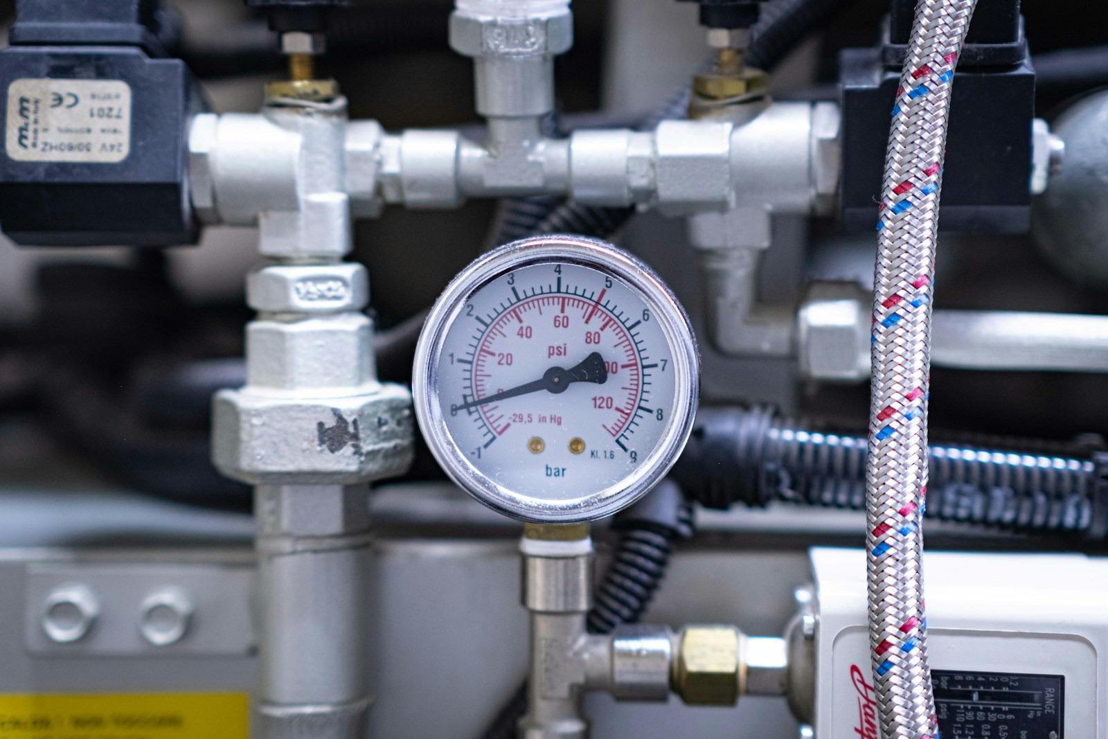
Determine the minimum operating pressure at the critical machine and add justified losses along its actual supply path. For example, an assumed 6.0 bar(g) machine requirement and an assumed 0.6 bar total path loss imply 6.6 bar(g) upstream during the design event; this arithmetic is not a recommended setting for every plant. Select dryer and filter capacities using their manufacturers’ correction factors for pressure and temperature. Confirm drain and purge air consumption where relevant.
Turn the calculation into an acceptance test
Ask the supplier to state delivered flow at the proposed pressure, minimum controllable output, peak response, required receiver arrangement and recovery behaviour. Log pressure at the receiver and critical user during a representative cycle. Check low-load operation as well as maximum production. Retain the spreadsheet assumptions or a signed demand schedule so that future expansion is based on an auditable starting point.
Sources and further reading
Prepared by the LeadCom editorial team from the references below. Selection checklists and examples are editorial guidance; final requirements depend on the process and equipment documentation.